
-
Products
-
Application


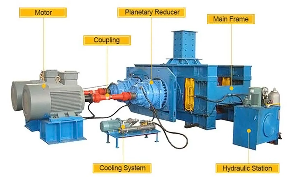
Calibrating the roll gap on a high-pressure grinding roll (HPGR) is a critical maintenance task for ensuring optimal performance, energy efficiency, and preventing damage. Here's a comprehensive guide on how to do it.

Performance: The gap directly influences the pressure applied to the material, affecting particle size reduction, throughput, and product quality.
Energy Efficiency: An incorrect gap (too wide or too narrow) leads to inefficient energy use.
Wear Management: Maintaining the correct gap and ensuring parallelism prevents uneven wear on the roll surfaces (tires/segments) and potential contact between the rolls, which can cause catastrophic damage.
Machine Protection: Ensures the hydraulic system operates within its design parameters and protects bearings and frame components from excessive stress.
Roll Gap (S): The minimum distance between the surfaces of the two counter-rotating rolls (one fixed, one floating/movable).
Operating Gap: The actual gap during operation under pressure, which might differ slightly from the static (no-load) gap due to system flex. Calibration typically refers to setting the static gap.
Parallelism: Ensuring the gap is consistent across the entire width of the rolls. Non-parallelism leads to uneven grinding, skewed wear, and potential machine stress.
Feeler Gauges (Most Common for Static Gap): Using precise metal strips of known thickness.
Lead Wire / Soft Metal Slugs: Compressing a soft material between the rolls and measuring its deformed thickness.
Mechanical Jigs/Templates: Using specialized tools provided by the OEM.
Electronic Measurement (Control System Reference): Some systems use sensors or a "roll touch" procedure as a zero reference, then apply an offset. This still requires physical verification.

Step-by-Step Calibration Procedure (General Guide - ALWAYS Prioritize Your OEM Manual):
SAFETY FIRST - Lockout/Tagout (LOTO): Absolutely critical. Isolate ALL energy sources (electrical, hydraulic, pneumatic) to the HPGR according to established site procedures before any work begins. Ensure the machine cannot be started accidentally.
Consult the OEM Manual: This is your primary resource. Procedures can vary significantly between manufacturers and models.
Gather Tools:
Appropriate measuring tools (calibrated feeler gauges, micrometer for lead wire, specific jigs).
Hand tools (wrenches, etc.) for accessing inspection points or making adjustments (if manual).
Cleaning supplies (rags, brushes, solvent if necessary) to clean roll surfaces.
Flashlight.
Personal Protective Equipment (PPE): Safety glasses, gloves, hard hat, steel-toed boots, hearing protection (if noise is present nearby).
LOTO kit.
Personnel: Ensure only trained and authorized personnel perform the calibration.
Machine State: Allow the machine to cool down if it has been operating recently. Ensure the area around the rolls is clean and accessible.
Know the Target Gap: Determine the required static roll gap setting based on operational requirements, feed material, desired product size, and OEM recommendations.
Access the Rolls: Safely open necessary inspection hatches or guards to gain visual and physical access to the gap between the rolls. Follow confined space entry procedures if required.
Clean Roll Surfaces: Thoroughly clean the roll surfaces where measurements will be taken. Any debris, caked material, or grease will lead to inaccurate readings.
Initial Measurement (Optional but Recommended): Measure the current gap before making any adjustments. This provides a baseline and helps understand any drift since the last calibration. Use the chosen method (e.g., feeler gauges) at multiple points across the width (both ends and the center). Note these values.
Identify Adjustment Mechanism: Understand how the gap is adjusted on your specific HPGR. This is usually via the hydraulic system controlled through the PLC/HMI, or sometimes via manual hydraulic pumps or mechanical screw jacks (less common on modern units).
Make Adjustments:
Hydraulic System (Most Common): Use the machine's control interface (HMI/PLC) to command the hydraulic cylinders controlling the floating roll position. Input the desired gap setting or make incremental adjustments.
Manual Adjustment: Follow the OEM procedure carefully using appropriate tools.
IMPORTANT: Adjustments should move the floating roll relative to the fixed roll. Ensure the system is designed to maintain parallelism or that adjustments are made evenly on both sides (if applicable).
Measure the Gap (Feeler Gauges):
Select the feeler gauge corresponding to the target gap.
Carefully insert the gauge into the gap between the rolls. It should slide in with slight resistance ("slip fit"). It should not be loose, nor should it require excessive force.

Measure at a minimum of three points across the roll width: Drive Side (DS), Non-Drive Side (NDS), and Center. Some procedures recommend five points.
Ensure the feeler gauge is inserted perpendicular to the roll axis.
Check for Parallelism: Compare the measurements across the roll width. They should be within the tolerance specified by the OEM (e.g., typically within 0.1mm - 0.5mm of each other, but check your manual).
Iterate if Necessary: If the gap is incorrect or not parallel:
Make further small, incremental adjustments using the control system or manual mechanism.
Re-measure carefully after each adjustment.
If parallelism is off, you may need to adjust individual hydraulic cylinders or sides (if the system allows) following the OEM procedure. This can be complex and might require specific diagnostic modes in the control system.
Final Verification: Once the target gap and parallelism are achieved and within tolerance, double-check the measurements one last time.
Secure Adjustments: Ensure any locking mechanisms (if present on manual systems) are properly secured.
Close Access Points: Safely close and secure all inspection hatches and guards. Remove all tools and cleaning materials from the area.
Remove LOTO: Follow the established site procedure to remove locks and tags and re-energize the machine.
Test Run (Recommended): Perform a brief no-load or light-load test run, monitoring the control system feedback (hydraulic pressures, gap sensors if equipped), listening for unusual noises, and checking for vibrations.
Documentation: Record everything meticulously:
Date and time of calibration.
Technician(s) performing the calibration.
HPGR unit identification.
Measurement method used (feeler gauge, lead wire, etc.).
Target gap setting.
Initial measured gap values (DS, Center, NDS).
Final measured gap values (DS, Center, NDS).
Any issues encountered and corrective actions taken.
Next scheduled calibration date.
Using Other Methods:
Lead Wire: Place short pieces of lead wire (or soft slugs) at measurement points across the roll width. Briefly jog the rolls together under very low, controlled pressure (follow OEM safety procedures exactly for this – jogging can be hazardous). Carefully retrieve the flattened wires/slugs and measure their thickness using a micrometer. Adjust and repeat as necessary. This method gives an average gap under slight pressure.
Mechanical Jigs: Use according to specific OEM instructions. They often provide a very precise physical reference.
Electronic/Control System: If the system uses a "zero point" (roll touch), this procedure must be done carefully as per the OEM, often involving setting hydraulic pressures to minimums. Crucially, always physically verify the resulting gap using feeler gauges or lead wire after performing an electronic calibration or zeroing procedure. Do not rely solely on the control system readout initially.
Frequency:
Calibration frequency depends on:
OEM recommendations.
Operating hours.
Material abrasiveness.
Monitoring of performance trends (product size, throughput, power draw).
After major maintenance (e.g., roll replacement/re-grinding).
Regular checks (e.g., weekly or monthly) and full calibration (e.g., quarterly, semi-annually, or based on wear) are common schedules.
Always prioritize safety and follow your specific HPGR's OEM manual. If in doubt, contact the manufacturer or a qualified service technician.
HPGR Wear Protection Solutions
No information

Official Agent of ZY MINING in Russia.
Please enter here.
Add: Luoxin Industrial Zone,Luoyang City,Henan Province P.R.C.
Tel: +86-379-67313306
E-mail: gloria@zyksjx.com